1. About Two Places and Three Centers
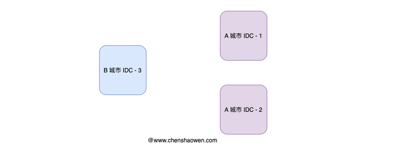
As shown above, the two-places-three-centers architecture exists to improve the fault tolerance and disaster recovery capability of a system. When one data center becomes unavailable, traffic for critical business can be switched to another data center, which makes the system resilient to city-level natural disasters.
The “two places” are two geographically distinct cities, and the “three centers” are:
- Production center
- Same-city disaster recovery center
- Remote disaster recovery center
2. Network Connectivity Between Data Centers
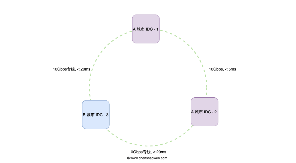
As shown above, a two-places-three-centers architecture presupposes that the data centers are interconnected. So we need to build a low-latency ring network. The fiber run is usually over 50 KM. If you lease a carrier’s dedicated line, the latency may be a little higher, but usually no more than 20 ms. For same-city fiber, latency is only around 3 ms.
We need to trade off the distance between data centers against latency:
- The farther apart the data centers, the stronger the disaster recovery capability, but the longer the fiber and the higher the latency
- The closer the data centers, the weaker the disaster recovery capability, but the shorter the fiber and the lower the latency
Between two data centers in the same city, network latency is very low and data consistency is very high. For the remote data center, because the distance is great, you can lease a dedicated line to interconnect with the other two data centers, avoiding excessive latency.
3. Distributing Application Traffic
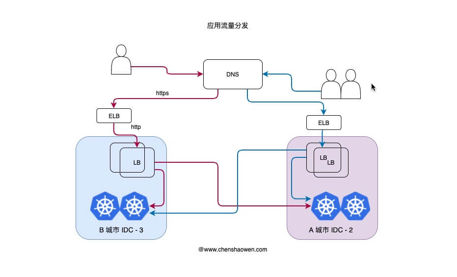
As shown above, this is the path traffic takes when a user accesses the application:
- The user accesses the application service through a domain name, which intelligent DNS resolves to the IP of the geographically closer data center
- The public cloud’s ELB offloads the TLS certificate and provides some security protection.
- Inside the data center, an LB service deployed on virtual machines splits the traffic, and part of the traffic is split off to the other data center. The LBs in the two data centers use the same storage backend.
- The services in the two data centers respond to different users’ requests
3.1 Why the Remote Data Center Carries Traffic
A path that has never been hit by traffic is not reliable. Even with high availability and disaster recovery in place, without regular drills the system will not have the ability to respond.
Therefore, when building multiple data centers, one very important point is to let more data centers receive access traffic. Here we chose the two remote data centers as the main day-to-day traffic data centers, for these reasons:
- Better rehearsal of what happens when disaster strikes
- After leasing dedicated lines, the remote data centers’ latency meets the requirement
- The budget is sufficient to buy dedicated-line bandwidth
3.2 Why There Is Still an LB Layer After DNS
There may be a question here: outside the data center DNS splits the traffic once, and inside the data center the LB splits the traffic again. The reasons are:
- DNS takes effect slowly; adding an LB layer lets traffic be switched faster
- Precisely control the proportion of traffic allocated to each data center
- Support canary releases of application versions by data center
4. Layering Stateful and Stateless
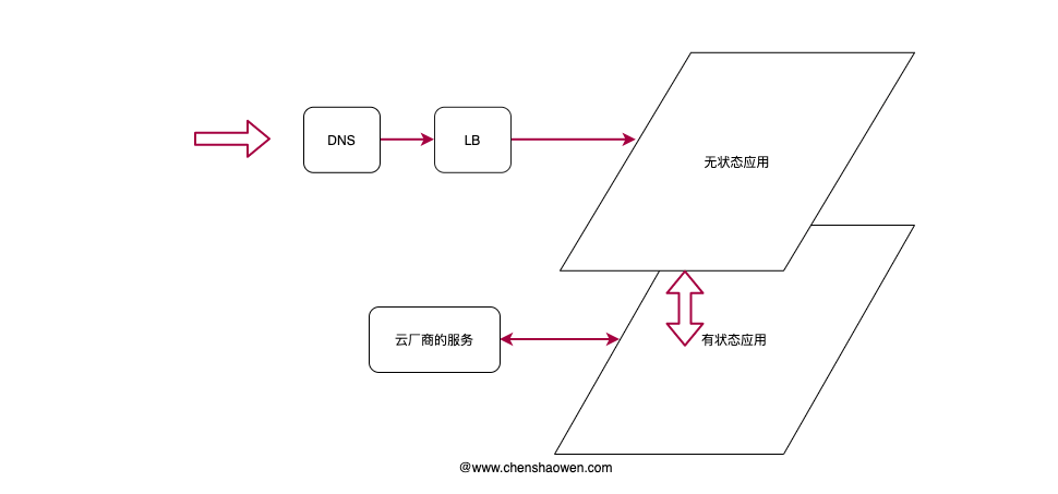
As shown above, layering stateful applications and stateless applications makes the service architecture clearer. Stateless applications provide services externally, while stateful applications provide services to the stateless applications.
The stateful applications here are high-availability services deployed on virtual machines, or middleware cloud services bought directly from a vendor.
4.1 Stateless Applications
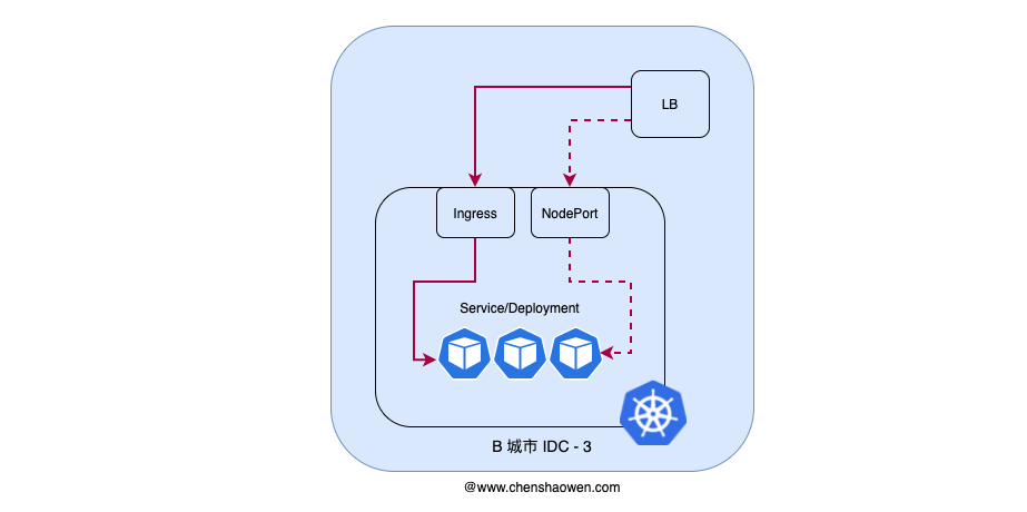
As shown above, stateless applications rely on Kubernetes to provide the runtime environment. Thanks to its powerful elasticity and self-healing, we only need to focus on using the various cloud-native components and tuning parameters to satisfy most business requirements.
For stateless applications, we usually expose services externally with Ingress or NodePort. The main differences between the two are:
- Number of services supported. Each NodePort occupies a port
- Feature differences. Ingress can provide Host, canary, sub-Path routing, and so on
- Number of components. Ingress needs more components to support it
- Operations cost. When Ingress is updated the blast radius is larger and the operations cost is high
- Migration cost. NodePort may run into port conflicts
Kubernetes does not guarantee 100% service availability; rather, when a service fails it can quickly create a new one using idle resources. At the same time, Kubernetes also faces problems such as cluster upgrades and host maintenance, so for some services that change infrequently and demand high stability, we use virtual machine deployment.
For example the LB here: an LB is an application with a large blast radius, and there will not be many of them, so we usually deploy it in a high-availability pattern across a few virtual machines.
4.2 Stateful Applications
- Image registry
Harbor high availability usually comes in two forms:
- Multiple independently deployed Harbors syncing in real time. Images may be inconsistent between different Harbor instances, with some delay.
- Multiple Harbors sharing one storage backend. Multiple Harbor instances sharing one storage backend guarantees data consistency, but places higher demands on the distributed storage backend.
Here we use Harbor shared-storage high availability + dragonFly. In the non-primary traffic data center, we deploy a high-availability Harbor, use dragonFly to distribute images to each data center, and the hosts in the data centers pull images through a mirror configured by dfget. As shown below:
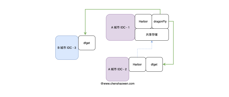
Using dragonFly to distribute images reduces the number of pulls for the same image when deploying multi-replica application instances, saving dedicated-line bandwidth.
- MySQL multi-data-center MHA high availability
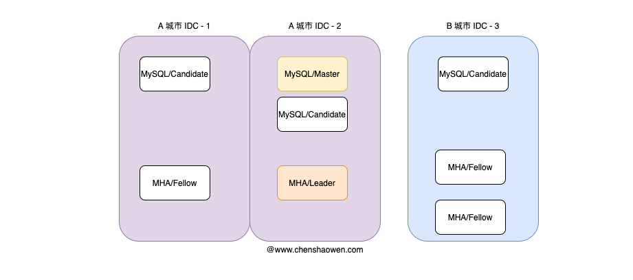
Compared with the use of PostgreSQL abroad, MySQL is used very widely in China. MHA (Master High Availability) is a mature MySQL solution. When MySQL fails, MHA can complete the database failover in under 30 seconds while preserving data consistency as much as possible.
- Redis multi-data-center cluster mode
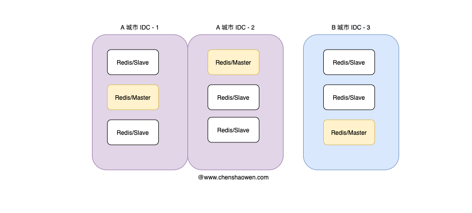
The Redis cluster achieves data sharing through sharding and provides replication and failover. Compared with sentinel mode, which has only one master, cluster mode has multiple masters and therefore high availability.
5. Summary
This post is a brief summary of the two-places-three-centers architecture. What is written is an abstraction of what was seen, and cannot fully describe the details. The main points are:
- The key to two places and three centers is to build a ring-shaped, interconnected data center network
- Stateful applications are deployed on virtual machines, stateless applications on Kubernetes
- Access traffic is first split to a data center by DNS, and then split to the various clusters by an LB inside the data center
