This article is translated from https://learnk8s.io/kubernetes-network-packets, not word for word, with some of my own understanding worked in.
By reading this article, you can learn how packets are forwarded inside and outside Kubernetes, starting from the original web request all the way to the container hosting the application.
Kubernetes Network Requirements
Before diving into the details of how packets flow through a Kubernetes cluster, let’s first clarify Kubernetes’ requirements for networking.
The Kubernetes network model defines a set of basic rules:
- Without using network address translation (NAT), a Pod in the cluster can communicate with any other Pod.
- Without using network address translation (NAT), a program running on a cluster node can communicate with any Pod on the same node.
- Every Pod has its own IP address (IP-per-Pod), and any other Pod can reach it through that same address.
These requirements do not constrain the implementation to any particular solution.
Instead, they describe the characteristics of cluster networking in general terms.
To satisfy these constraints, you must solve the following challenges:
- How do you ensure that containers in the same Pod behave as if they were on the same host?
- Can Pods in the cluster reach other Pods?
- Can Pods access Services? Are Services load balanced?
- Can Pods receive traffic from outside the cluster?
In this article, we will focus on the first three points, starting with networking inside a Pod and container-to-container communication.
How Linux Network Namespaces Work in a Pod
Let’s look at a main container running an application together with a companion container.
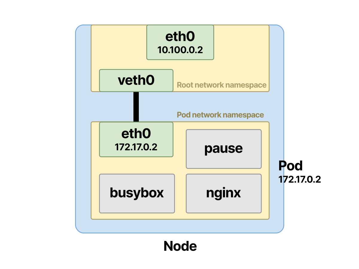
In the example, there is a Pod with an nginx and a busybox container:
| |
When it is deployed, the following happens:
- The Pod gets its own network namespace on the node.
- An IP address is assigned to the Pod, and the two containers share ports between them.
- The two containers share the same network namespace and are visible to each other locally.
The network configuration is completed quickly in the background.
But let’s step back and try to understand why running a container requires the actions above.
In Linux, a network namespace is an independent, isolated logical space.
You can think of a network namespace as an independent piece carved out of a physical network interface.
Each piece can be configured separately and has its own network rules and resources.
These include firewall rules, interfaces (virtual or physical), routes, and everything else related to networking.
- The physical network interface holds the root network namespace.
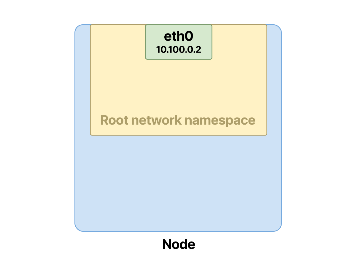
- You can use Linux network namespaces to create independent networks. Each network is isolated by default and will not communicate with others unless you configure it to.
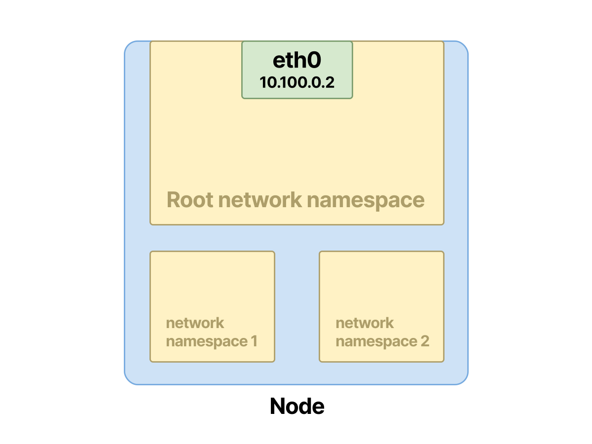
But in the end, the physical interface still has to handle all real packets, and all virtual interfaces are created on top of the physical interface.
Network namespaces can be managed with ip-netns, and ip netns list lists the namespaces on the host.
Note that created network namespaces appear under
/var/run/netns, but Docker does not follow this rule.
For example, these are some namespaces on a Kubernetes node:
| |
Note the cni- prefix; it means the namespace was created by a CNI plugin.
When you create a Pod and the Pod is assigned to a node, the CNI will:
- Allocate an IP address.
- Connect the containers to the network.
If a Pod contains multiple containers, then all of those containers will be placed in the same namespace.
- When a Pod is created, the container runtime creates a network namespace for the containers.
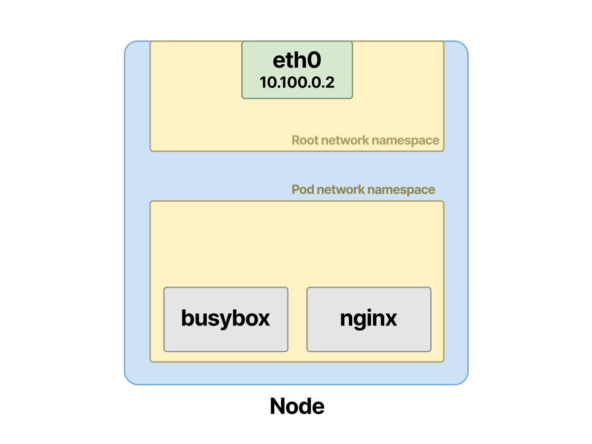
- Then the CNI is responsible for assigning an IP address to the Pod.
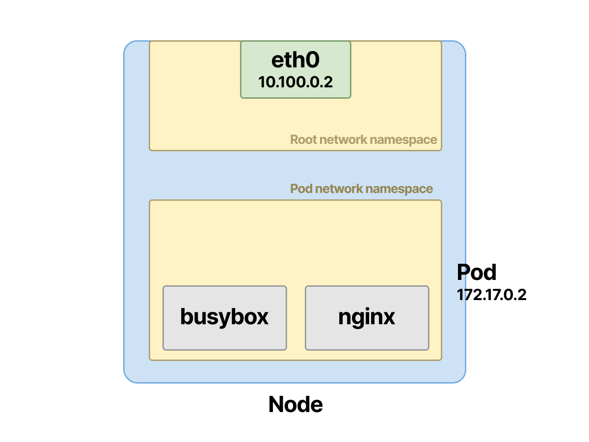
- Finally the CNI connects the containers to the rest of the network.
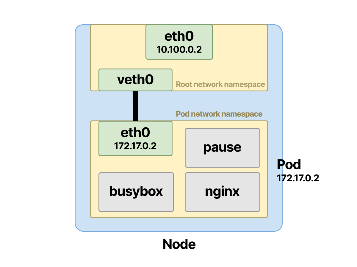
So what happens when you list the namespaces of the containers on a node?
You can SSH into a Kubernetes node and look at the namespaces:
| |
lsns is a command used to list all available namespaces on the host.
Keep in mind that Linux has several types of namespaces.
Where is the Nginx container?
What are those pause containers?
In a Pod, the pause Container Creates the Network Namespace
First list all the namespaces on the node and see whether you can find the Nginx container:
| |
The Nginx container is in the mount (mnt), Unix time-sharing (uts), and PID (pid) namespaces, but not in the network namespace (net).
Unfortunately, lsns only shows the smallest PID for each process, but you can filter further based on that process ID.
Use the following command to find the Nginx container across all namespaces:
| |
The pause process shows up again, and it has hijacked the network namespace.
What is going on?
Every Pod in the cluster has an extra hidden container running in the background, called the pause container.
List the containers running on the node and get the pause containers:
| |
As you can see, every Pod on the node has a corresponding pause container.
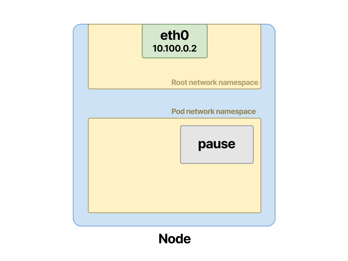
This pause container is responsible for creating and holding the network namespace.
The underlying container runtime performs the creation of the network namespace, usually by containerd or CRI-O.
The network namespace is created by the runtime before the Pod is deployed and the containers are created.
The container runtime does all of this automatically; you do not need to manually run ip netns to create namespaces.
Back to the pause container.
It contains very little code and goes to sleep immediately after deployment.
But it is essential and plays a crucial role in the Kubernetes ecosystem.
- When a Pod is created, the container runtime creates a network namespace with a sleeping container.
- The other containers in the Pod then join the network namespace created by the pause container.
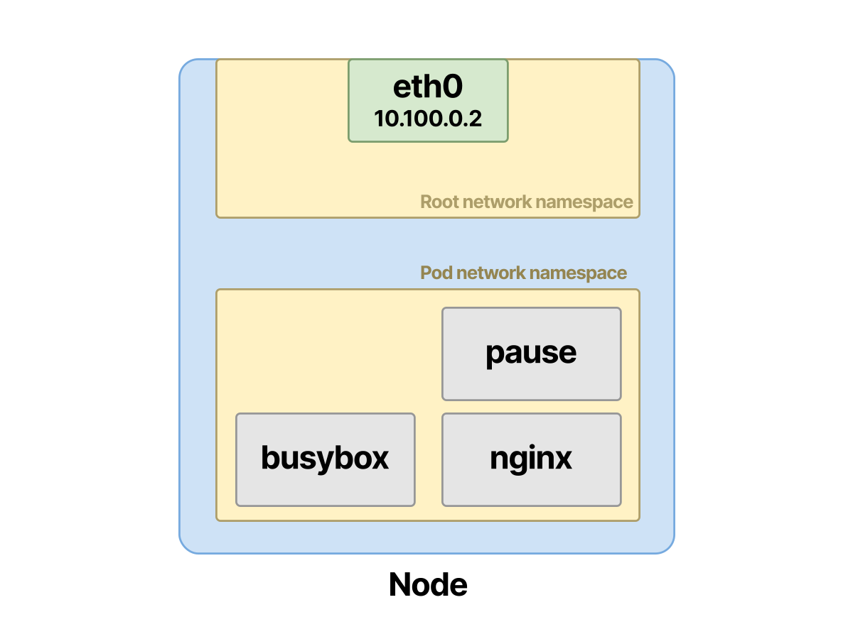
- At that point, the CNI assigns an IP address and connects the containers to the network.
What use is a container that goes to sleep?
To understand its purpose, let’s imagine a Pod with two containers, like the earlier example, but without the pause container.
Once the containers start, the CNI would:
- Make the busybox container join the previous network namespace.
- Assign an IP address.
- Connect the containers to the network.
What if Nginx crashes?
The CNI would have to perform all the steps again, and the networking of both containers would be disrupted.
Since a sleeping container is unlikely to have any errors, creating the network namespace this way is usually a safer and more robust choice.
If one container in a Pod crashes, the remaining ones can still answer other network requests.
Assigning an IP Address to a Pod
Earlier I mentioned that the Pod and its two containers share the same IP address.
How is that configured?
Inside the Pod's network namespace, an interface is created and an IP address is assigned.
Let’s verify it.
First, find the Pod’s IP address:
| |
Next, find the related network namespace.
Since network namespaces are created from the physical interface, you need to access the cluster node first.
If you are running minikube, use
minikube sshto access the node. If you are running in a cloud provider, there should be some way to access the node over SSH.
Once in, find the most recently created network namespace:
| |
In the example, it is cni-0f226515-e28b-df13-9f16-dd79456825ac. Then you can run an exec command inside that namespace:
| |
That IP is the Pod’s IP address! Find the network interface by looking up 12 in @if12
| |
You can also verify that the Nginx container is listening for HTTP traffic from within that namespace:
| |
If you cannot SSH into the worker nodes in the cluster, you can use
kubectl execto get a shell into the busybox container and run theipandnetstatcommands directly inside it.
We have just covered communication between containers, so let’s look at how to establish Pod-to-Pod communication.
Looking at Pod-to-Pod Traffic in the Cluster
Pod-to-Pod communication has two possible cases:
- The Pod traffic is destined for a Pod on the same node.
- The Pod traffic is destined for a Pod on a different node.
The whole workflow depends on virtual interface pairs and bridges, so let’s understand that part first.
For a Pod to communicate with another Pod, it must first reach the node's root namespace.
The connection between the Pod and the root namespace is made through a virtual Ethernet pair.
These virtual interface devices (the v in veth) connect and act as a tunnel between the two namespaces.
Using this veth device, you connect one end to the Pod’s namespace and the other end to the root namespace.
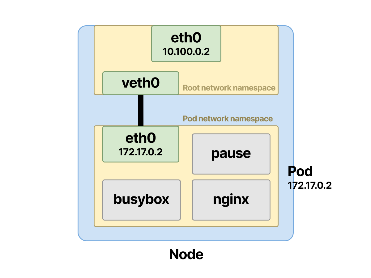
The CNI can do this for you, but you can also do it manually:
| |
Now the Pod’s namespace has a tunnel to the root namespace.
On a node, every newly created Pod gets a veth pair like this.
One is creating the interface pair; the other is assigning an address to the Ethernet device and configuring the default route.
Here is how to set up the veth1 interface in the Pod’s namespace:
| |
On the node, let’s create the other side, veth2:
| |
You can inspect the existing veth pairs as before.
In the Pod’s namespace, retrieve the suffix of the eth0 interface.
| |
In this case, you can find it with the command grep -A1 ^12 (or scroll to where the target is):
| |
You can also use the
ip -n cni-0f226515-e28b-df13-9f16-dd79456825ac link show type vethcommand.
Note the symbols on the 3: eth0@if12 and 12: cali97e50e215bd@if3 interfaces.
From the Pod namespace, the eth0 interface connects to interface number 12 in the root namespace, hence @if12.
At the other end of the veth pair, the root namespace connects to interface number 3 in the Pod namespace.
Next is the bridge that connects the two ends of the veth pair.
The Pod Network Namespace Connects to the Ethernet Bridge
The bridge aggregates every virtual interface located in the root namespace. This bridge allows traffic between the virtual pairs, and also allows traffic that passes through the shared root namespace.
Let’s add some background on how this works.
The Ethernet bridge operates at layer 2 of the OSI network model.
You can think of the bridge as a virtual switch that accepts connections from different namespaces and interfaces.
An Ethernet bridge can connect multiple available networks on a node.
Therefore, you can use a bridge to connect two interfaces, that is, the veth of one Pod namespace to the veth of another Pod on the same node.
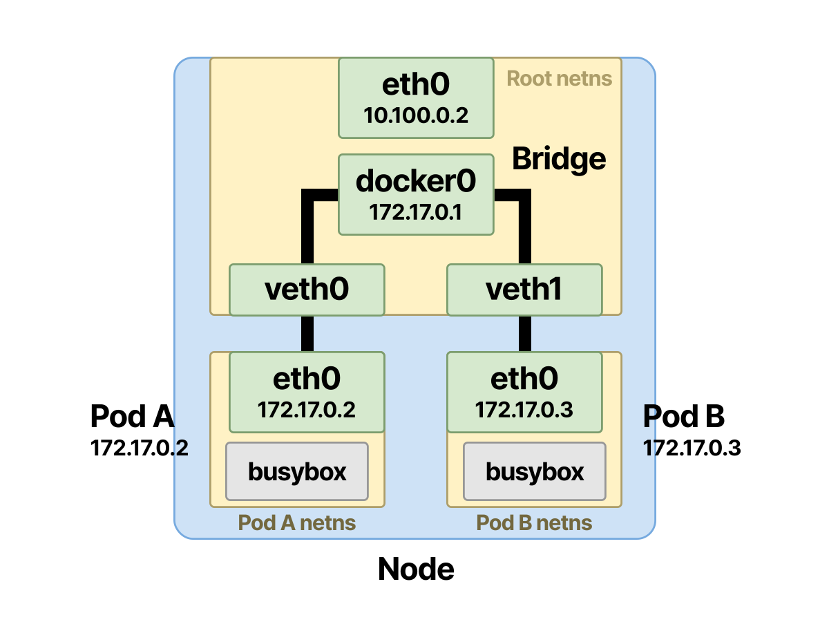
Next, let’s continue to look at the purpose of the bridge and the veth pair.
Tracing Pod-to-Pod Traffic on the Same Node
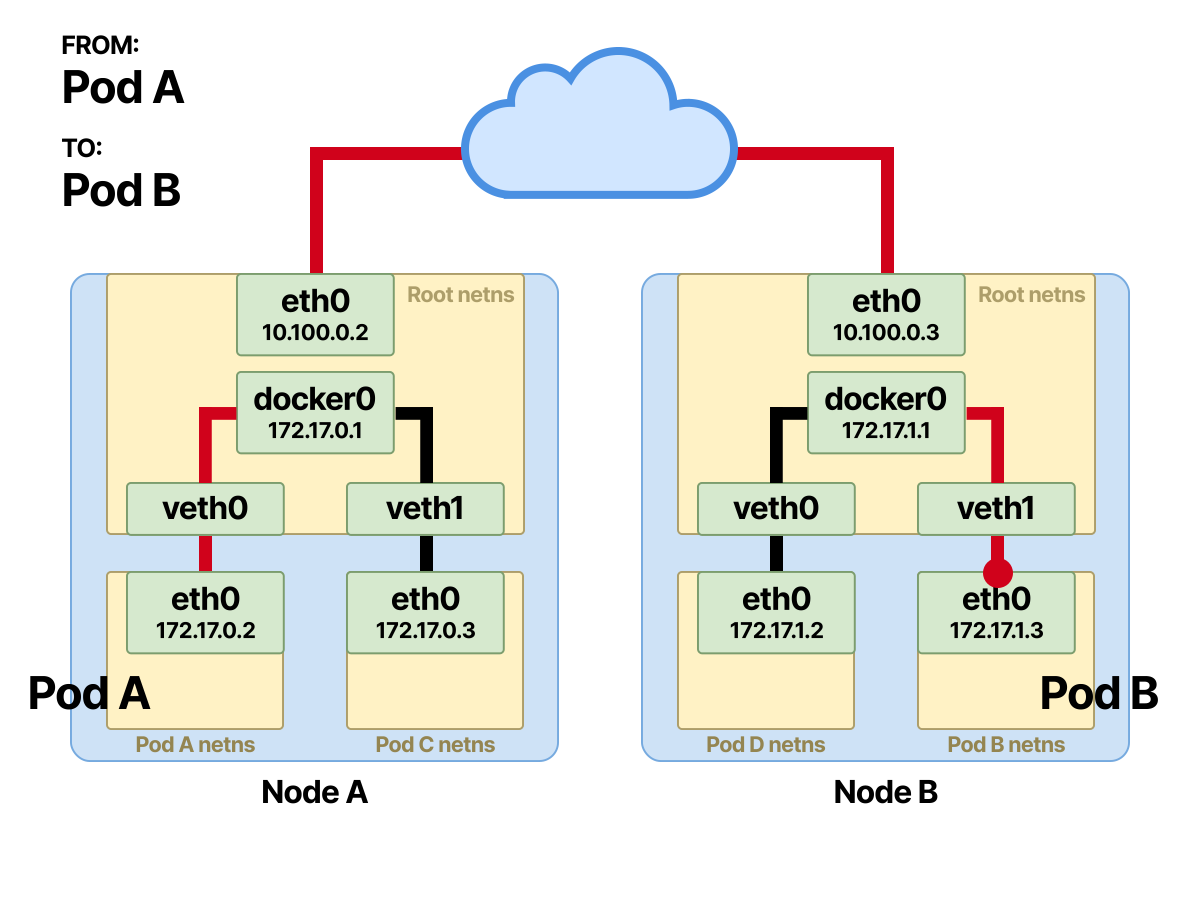
Suppose there are two Pods on the same node, and Pod-A sends a message to Pod-B.
- Since the destination is not in the same namespace, Pod-A sends the packet to its default interface eth0. This interface is bound to one end of the veth pair and acts as a tunnel. In this way, the packet is forwarded to the root namespace on the node.
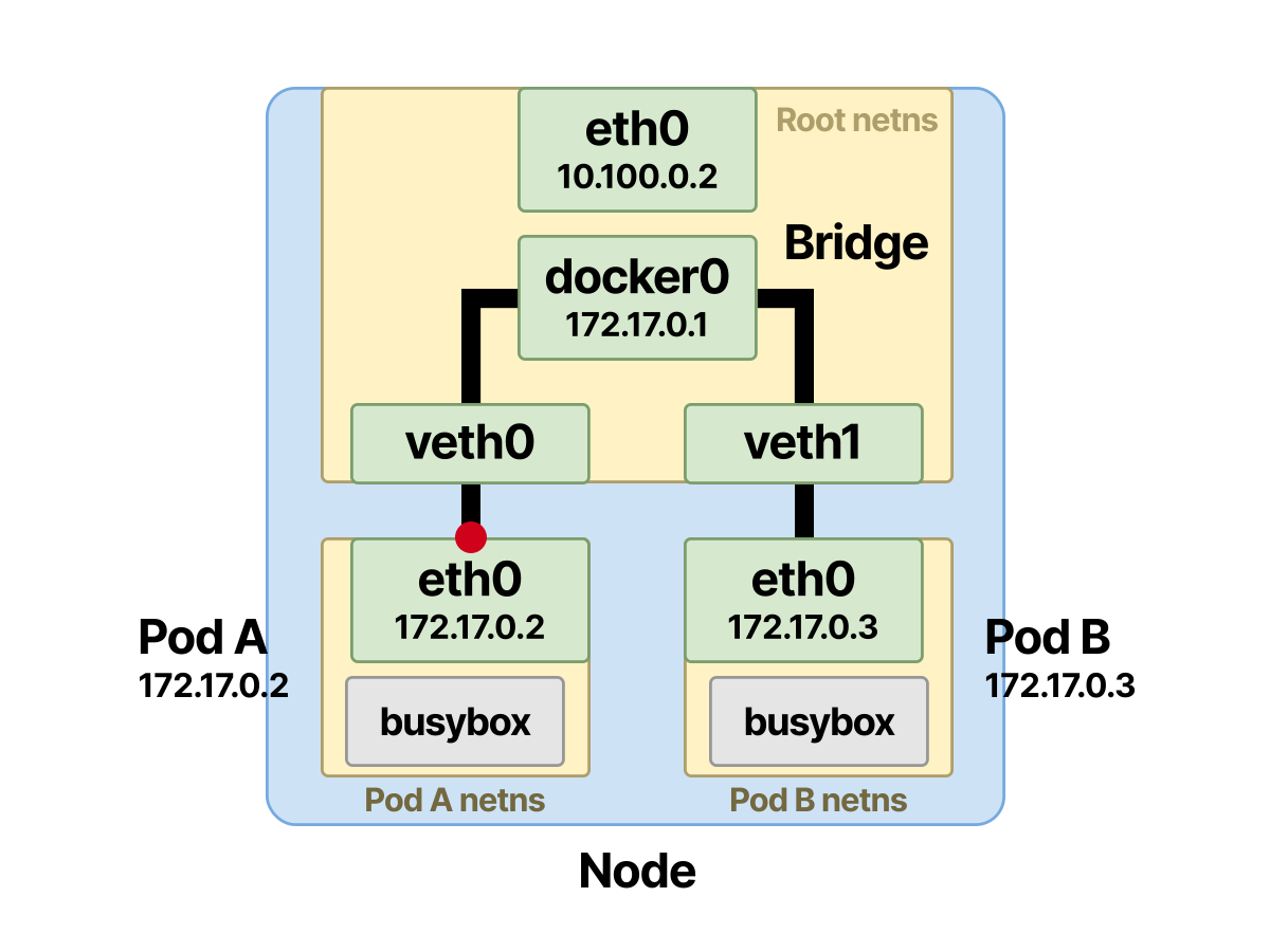
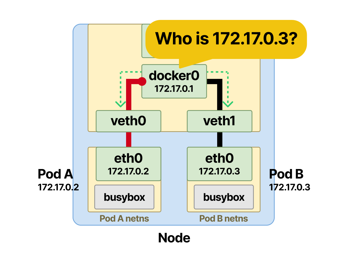
- The Ethernet bridge acts as a virtual switch and needs the MAC address of the destination Pod-B in order to work.
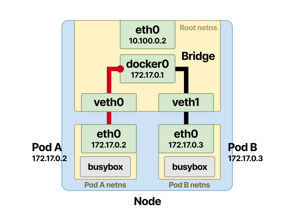
- The ARP protocol solves this. When the frame reaches the bridge, an ARP broadcast is sent to all connected devices. The bridge broadcasts asking who holds Pod-B’s IP address
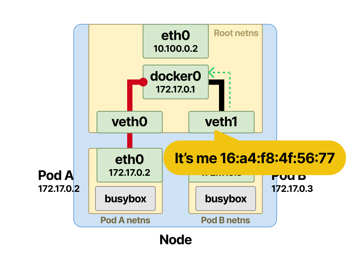
- A reply comes back with the MAC address that owns Pod-B’s IP, and this information is stored in the bridge’s ARP cache (lookup table).
- Once the mapping between IP address and MAC address is stored, the bridge looks it up in the table and forwards the packet to the correct endpoint. After the packet reaches the
vethof Pod-B inside the root namespace, it soon arrives at the eth0 interface inside Pod-B’s namespace.
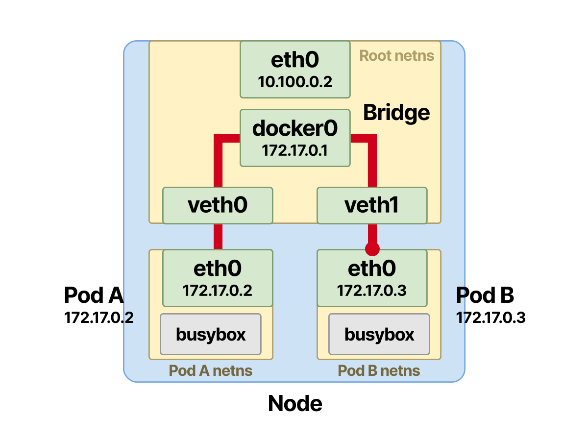
At this point, the communication between Pod-A and Pod-B has succeeded.
Tracing Pod-to-Pod Communication Across Different Nodes
For communication between Pods on different nodes, there are additional hops.
- The first few steps stay the same, until the packet reaches the root namespace and needs to be sent to Pod-B.
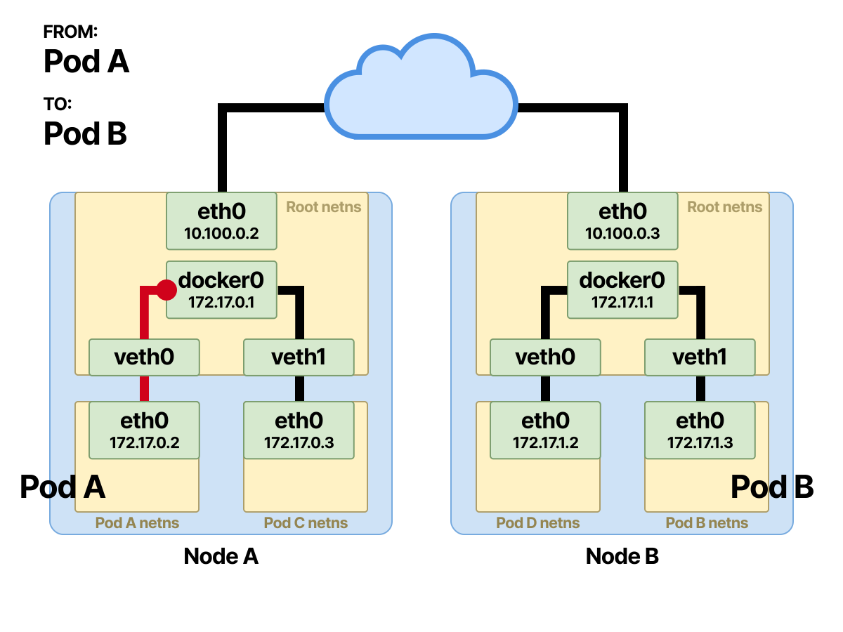
- When the destination IP is not in the local network, the packet is forwarded to the node’s default gateway. The node’s egress gateway, or default gateway, is usually on the physical interface eth0 that connects the node to the network.
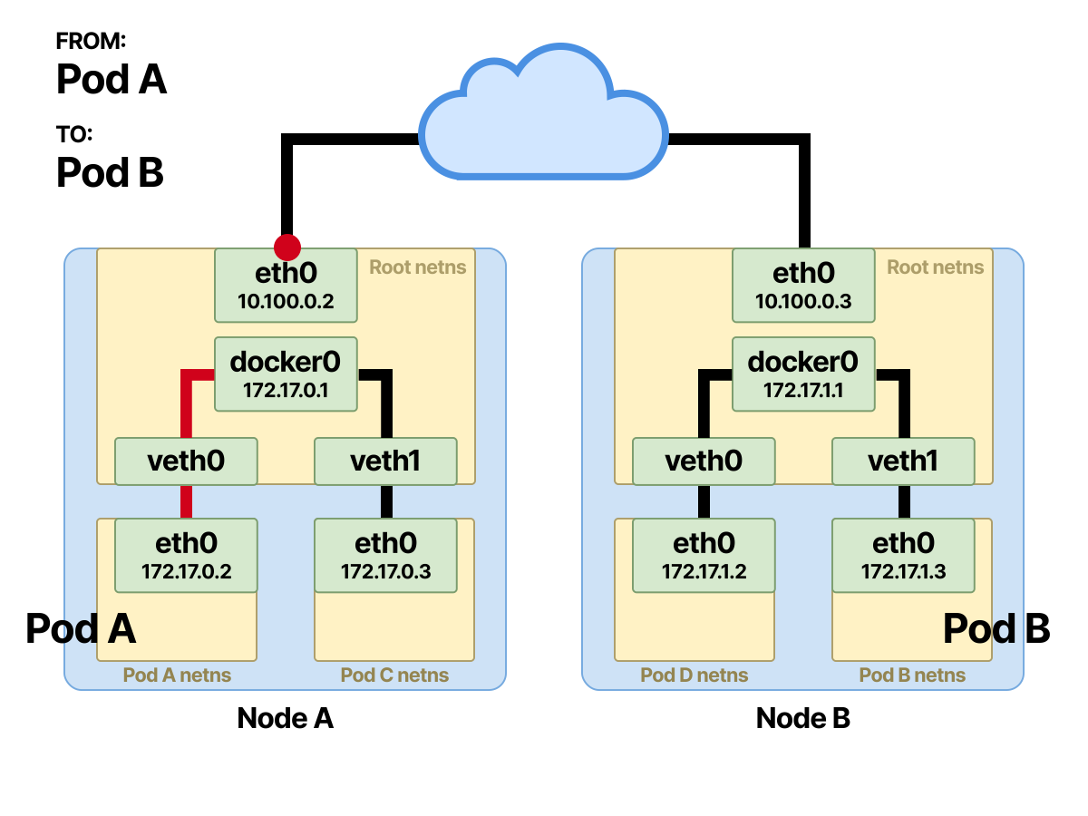
At this point no ARP resolution happens, because the source IP and the destination IP are not in the same subnet.
The subnet check is done using bitwise operations.
When the destination IP is not in the current subnet, the packet is forwarded to the node’s default gateway.
How Bitwise Operations Work
When determining where to forward a packet, the source node must perform a bitwise operation
This is also known as an AND operation.
As a refresher, the rules of the bitwise AND operation:
0 AND 0 = 0
0 AND 1 = 0
1 AND 0 = 0
1 AND 1 = 1
Anything other than 1 AND 1 is false.
If the source node’s IP is 192.168.1.1 with a subnet mask of /24, and the destination IP is 172.16.1.1/16, the bitwise AND operation will show that they are on different subnets.
This means the destination IP is not on the same network as the packet’s source, and the packet will be forwarded through the default gateway.
Math time.
We have to start from the 32-bit binary addresses and perform the AND operation.
First find the source IP network and the destination IP network.
| Type | Binary | Converted |
|---|---|---|
| Src. IP Address | 11000000.10101000.00000001.00000001 | 192.168.1.1 |
| Src. Subnet Mask | 11111111.11111111.11111111.00000000 | 255.255.255.0(/24) |
| Src. Network | 11000000.10101000.00000001.00000000 | 192.168.1.0 |
| Dst. IP Address | 10101100.00010000.00000001.00000001 | 172.16.1.1 |
| Dst. Subnet Mask | 11111111.11111111.00000000.00000000 | 255.255.0.0(/16) |
| Dst. Network | 10101100.00010000.00000000.00000000 | 172.16.0.0 |
After the bitwise operation, you need to compare the destination IP with the subnet of the packet’s source node.
| Type | Binary | Converted |
|---|---|---|
| Dst. IP Address | 10101100.00010000.00000001.00000001 | 172.16.1.1 |
| Src. Subnet Mask | 11111111.11111111.11111111.00000000 | 255.255.255.0(/24) |
| Network Result | 10101100.00010000.00000001.00000000 | 172.16.1.0 |
The result of the operation is 172.16.1.0, which is not equal to 192.168.1.0 (the source node’s network). This shows that the source IP address and the destination IP address are not on the same network.
If the destination IP were 192.168.1.2, that is, in the same subnet as the sending IP, the AND operation would yield the node’s local network.
| Type | Binary | Converted |
|---|---|---|
| Dst. IP Address | 11000000.10101000.00000001.00000010 | 192.168.1.2 |
| Src. Subnet Mask | 11111111.11111111.11111111.00000000 | 255.255.255.0(/24) |
| Network | 11000000.10101000.00000001.00000000 | 192.168.1.0 |
After the bit-by-bit comparison, ARP looks up the MAC address of the default gateway in its lookup table.
If there is an entry, the packet is forwarded immediately.
Otherwise, a broadcast is sent first to find the gateway’s MAC address.
- Now the packet is routed to another node’s default interface, which we’ll call Node-B.
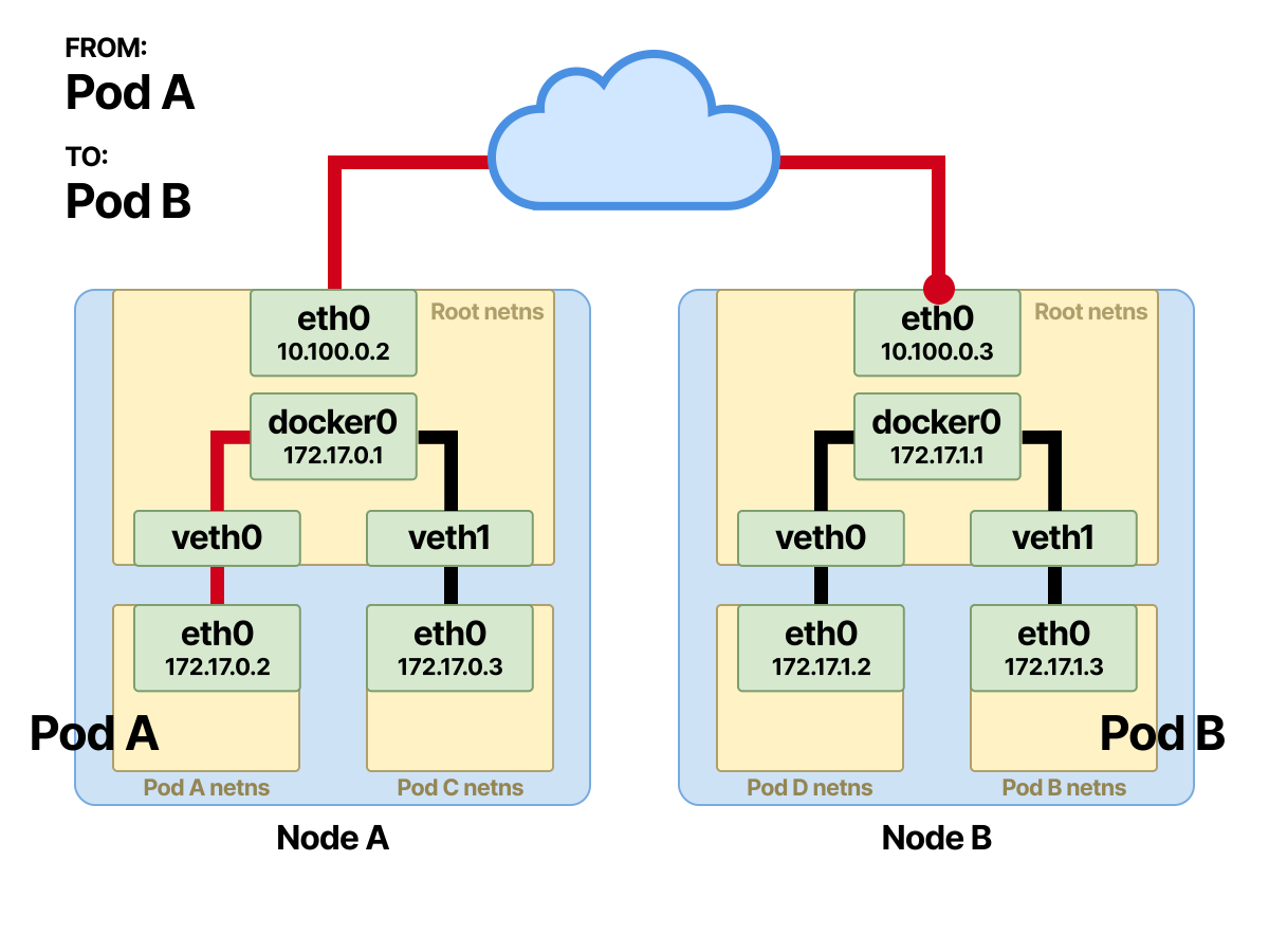
- In reverse order. Now the packet is in Node-B’s root namespace and arrives at the bridge, where ARP resolution happens.
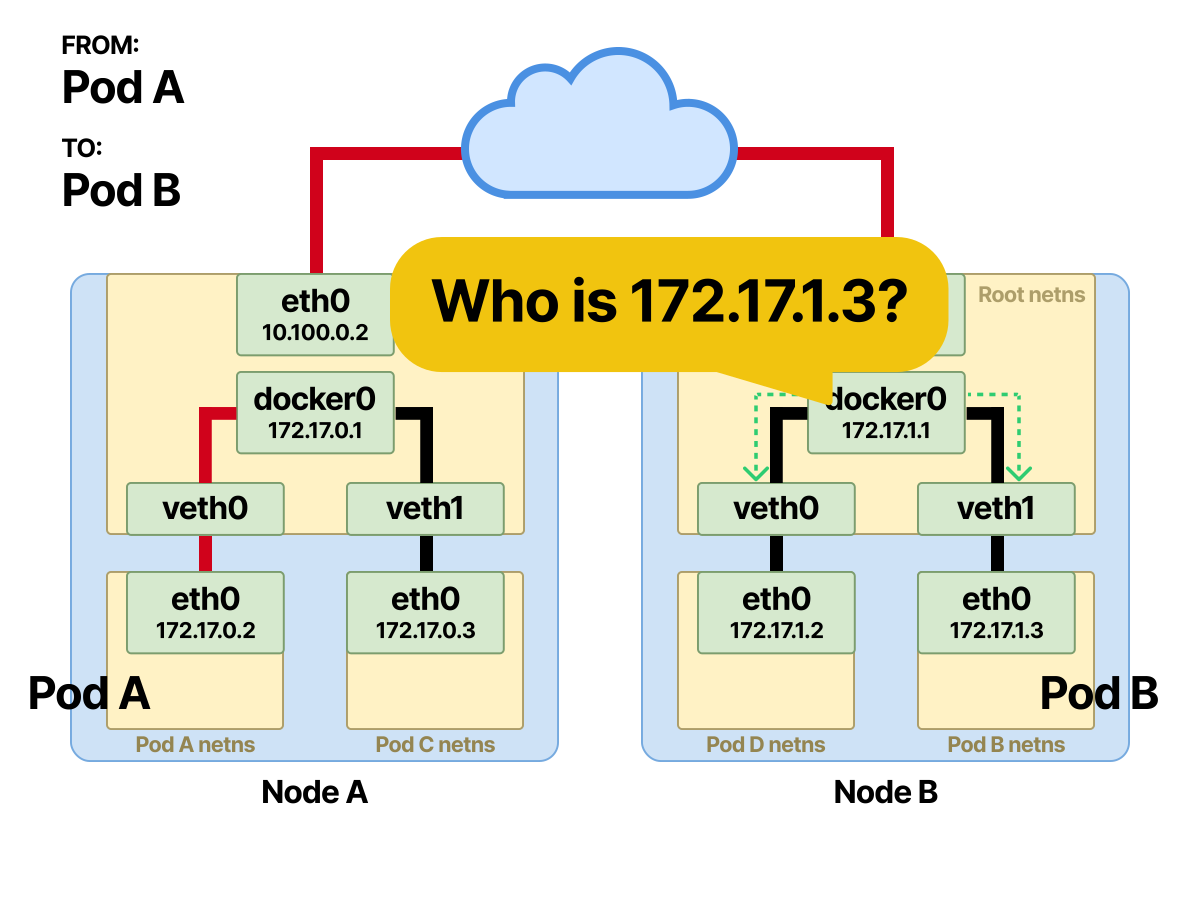
- The routing system returns the MAC address of the interface connected to Pod-B.
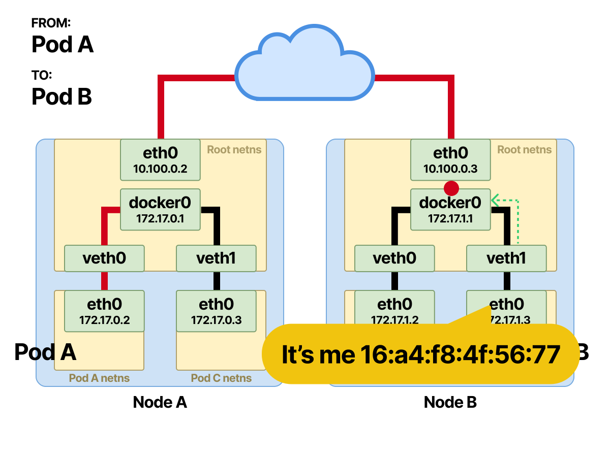
- The bridge forwards the frame through Pod-B’s
vethdevice and it reaches Pod-B’s namespace.
By now you should be familiar with how traffic between Pods flows. Next, let’s take a moment to look at how the CNI manages all of the above.
Container Network Interface - CNI
The Container Network Interface (CNI) focuses mainly on networking within the current node.
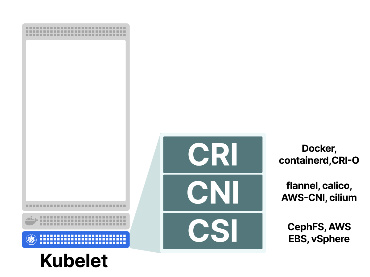
You can think of the CNI as a set of rules to follow in order to solve Kubernetes’ networking needs.
These CNI implementations are available:
They all follow the same CNI standard.
Without a CNI, you would have to do the following manually:
- Create interfaces.
- Create veth pairs.
- Set up network namespaces.
- Set up static routes.
- Configure Ethernet bridges.
- Assign IP addresses.
- Create NAT rules.
- And a great many other things.
That is not even counting the fact that when a Pod is deleted or restarted, all of the same operations have to be repeated.
The CNI must support four different operations:
- ADD - Add a container to the network.
- DEL - Remove a container from the network.
- CHECK - Return an error if there is a problem with the container’s network.
- VERSION - Show the plugin’s version.
Let’s look together at how the CNI works.
When a Pod is assigned to a particular node, Kubelet itself does not initialize the network.
Instead, Kubelet hands this task to the CNI.
However, Kubelet specifies the configuration in JSON format and sends it to the CNI plugin.
You can go into the /etc/cni/net.d folder on the node and use the following command to view the current CNI configuration file:
| |
Each CNI plugin uses a different kind of network configuration.
For example, Calico uses BGP-based layer 3 networking to connect Pods
Cilium uses an eBPF-based overlay network from layer 3 up to layer 7
Like Calico, Cilium also supports restricting traffic by configuring network policies.
So which one should you use? There are mainly two categories of CNI.
In the first category, the CNI uses basic networking (also called a flat network) and assigns IP addresses to Pods from the cluster’s IP pool.
This approach can quickly exhaust IP addresses and become a burden.
In contrast, the other category uses an overlay network.
Simply put, an overlay network is a network built on top of the main (underlay) network.
An overlay network works by encapsulating packets from the underlay network, which are then sent to a Pod on another node.
A popular technology for overlay networks is VXLAN, which can tunnel an L2 domain over an L3 network.
So which is better?
There is no single answer; it depends on your needs.
Are you building a large cluster with tens of thousands of nodes?
Perhaps an overlay network is better.
Do you care about simpler configuration and inspecting network traffic, and are unwilling to lose that ability in a complex network?
A flat network suits you better.
Now that we have finished with the CNI, let’s look at how Pod-to-Service communication is wired up.
Examining Pod-to-Service Traffic
Because Pods are dynamic in Kubernetes, the IP addresses assigned to Pods are not static.
Pod IPs are ephemeral and change every time a Pod is created or deleted.
Services in Kubernetes solve this problem by providing a reliable mechanism for connecting to a group of Pods.
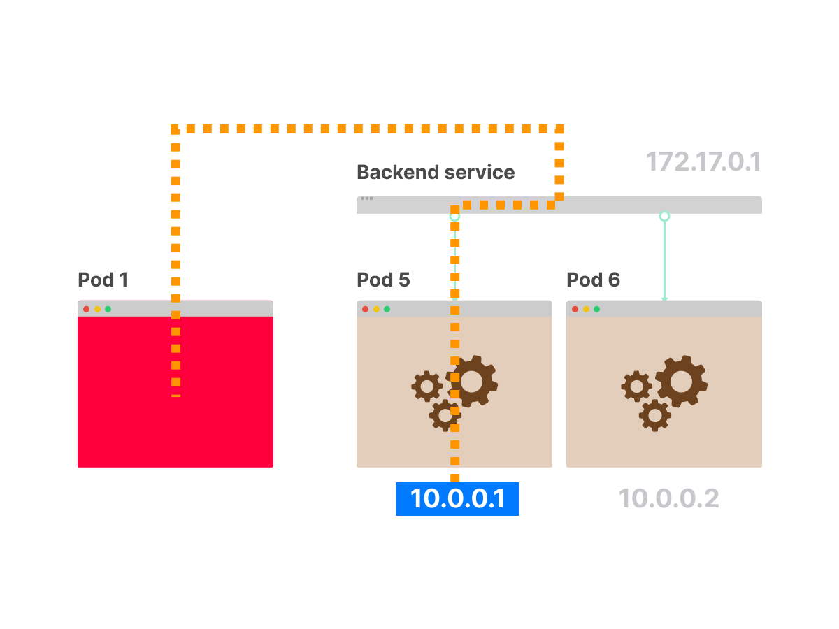
By default, when you create a Service in Kubernetes, it is assigned a virtual IP.
In a Service, you can use a selector to associate the Service with target Pods.
What happens when a Pod is deleted or added?
The Service's virtual IP stays static and unchanged.
But traffic can reach the newly created Pod without any intervention.
In other words, a Service in Kubernetes is similar to a load balancer.
But how do they work?
Intercepting and Rewriting Traffic with Netfilter and Iptables
Services in Kubernetes are built on two components in the Linux kernel:
Netfilter is a framework that can configure packet filtering, create NAT and port forwarding rules, and manage traffic in the network
In addition, it can block and deny unauthorized access.
On the other hand, iptables is a userspace program that can be used to configure IP packet filtering rules for the Linux kernel firewall.
iptables is implemented as different Netfilter modules.
You can use the iptables CLI to modify filtering rules on the fly and insert them into the netfilter mount points.
Filters are configured in different tables, which contain chains used to process network traffic packets.
Different protocols use different kernel modules and programs.
When iptables is mentioned, it usually means IPv4. For IPv6, the terminal tool is ip6tables.
iptables has five chains, each of which maps directly to a Netfilter hook.
From iptables’ point of view, they are:
PRE_ROUTINGINPUTFORWARDOUTPUTPOST_ROUTING
They map to the Netfilter hooks as follows:
NF_IP_PRE_ROUTINGNF_IP_LOCAL_INNF_IP_FORWARDNF_IP_LOCAL_OUTNF_IP_POST_ROUTING
When a packet arrives, depending on the stage it is in, a Netfilter hook is “triggered.” This hook executes specific iptables filtering rules.
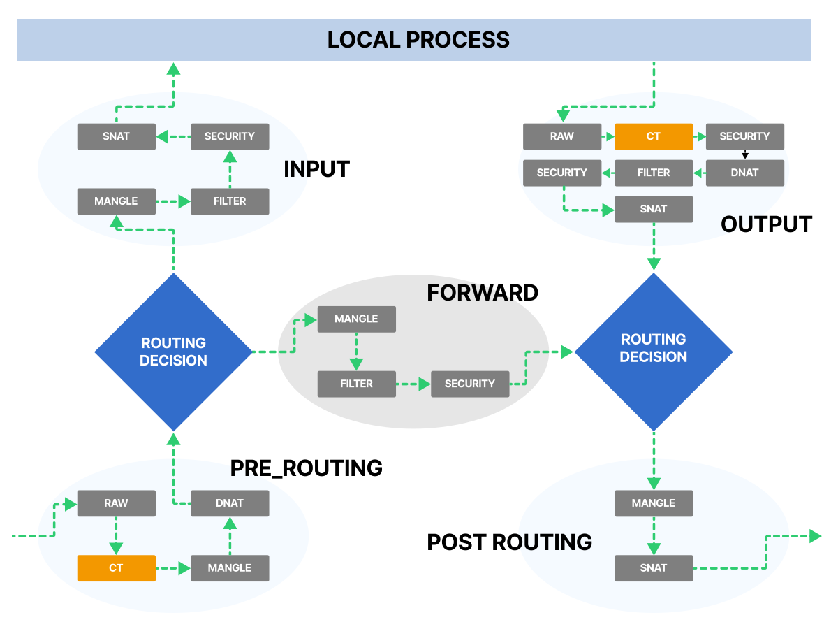
Whoa! This looks complicated!
But there is nothing to worry about.
This is why we use Kubernetes — all of the above is abstracted away through Services, and a simple YAML definition can set up these rules automatically.
If you are interested in looking at the iptables rules, you can connect to a node and run:
| |
You can also use this tool to visualize the iptables chains on a node.
Here is an example diagram visualizing iptables chains from a GKE node:
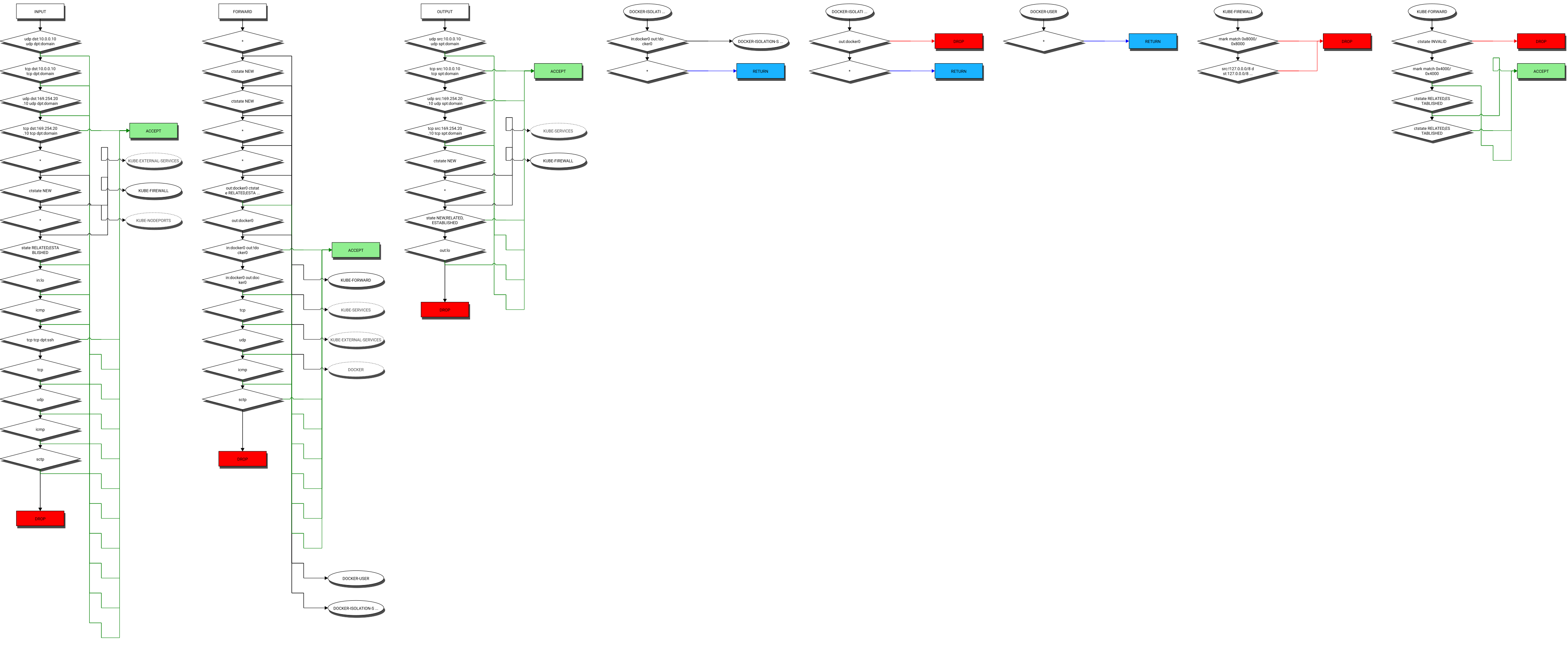
Note that hundreds of rules may be configured here; imagine setting that up by hand!
By now we have learned how Pods on the same node and Pods on different nodes communicate.
In Pod-to-Service communication, the first half of the path is the same.
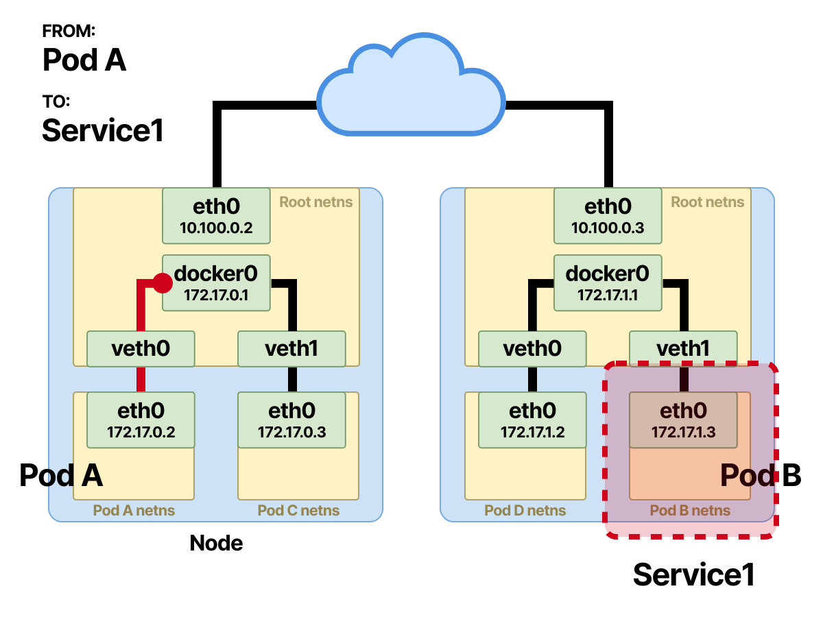
When a request travels from Pod-A toward Pod-B, since Pod-B is “behind” a Service, there are some differences along the way.
The original request is sent out on Pod-A’s eth0 interface in its namespace.
The request then travels through the veth to the bridge in the root namespace.
Once it reaches the bridge, the packet is immediately forwarded through the default gateway.
As in the Pod-to-Pod section, the host performs a bitwise comparison. Since the Service’s virtual IP is not part of the node CIDR, the packet is immediately forwarded through the default gateway.
If the default gateway’s MAC address is not yet in the lookup table, ARP resolution is performed to find the default gateway’s MAC address.
Now the magic happens.
Before the packet passes through the node’s routing, the Netfilter NF_IP_PRE_ROUTING hook is triggered and executes an iptables rule. This rule modifies Pod-A’s packet by changing the destination IP address, a DNAT.
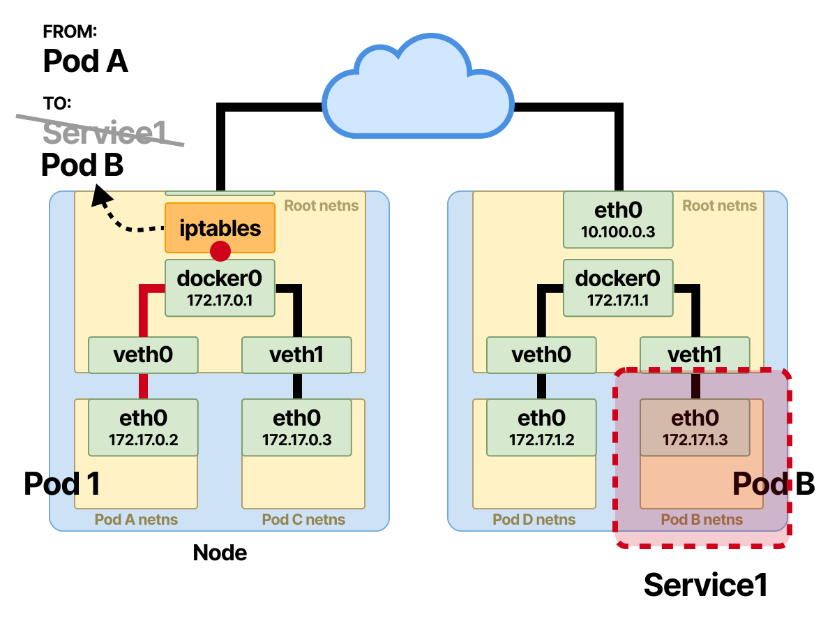
The Service’s virtual IP address from before is rewritten to Pod-B’s IP address.
Next, the packet routing process is the same as Pod-to-Pod communication.
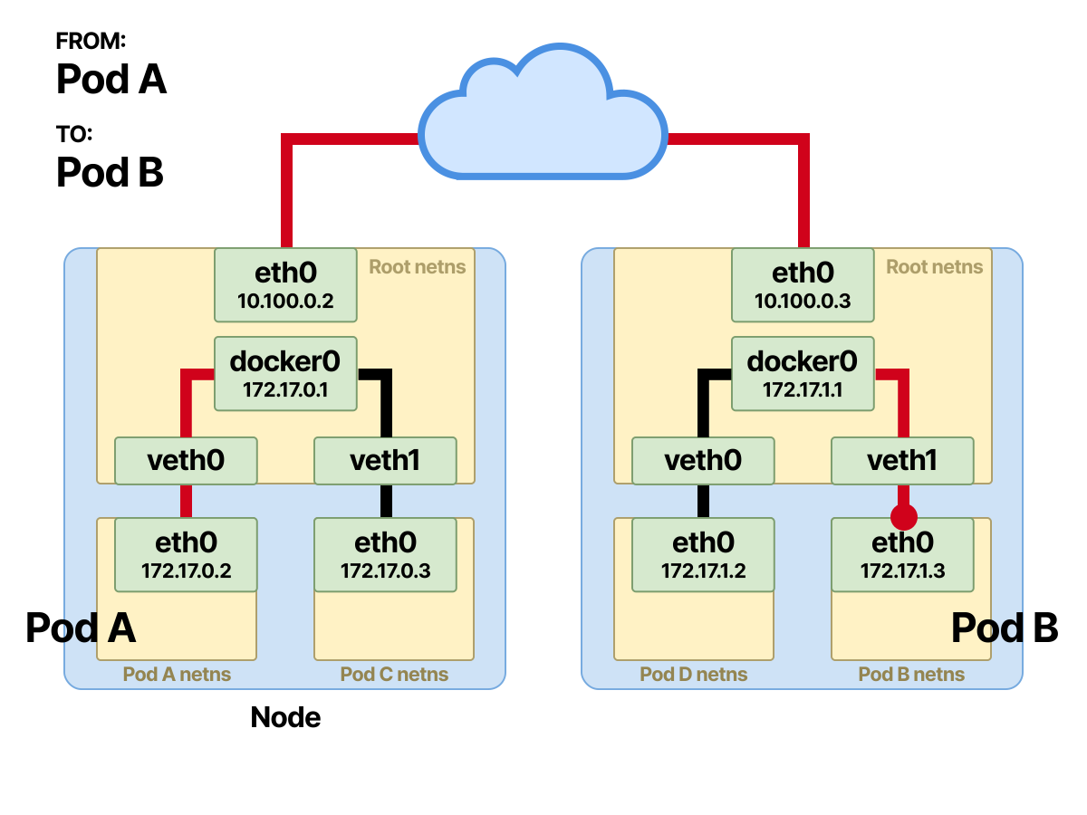
After the packet is rewritten, the communication is Pod-to-Pod.
However, throughout all this communication, a third-party feature is used.
This feature is called conntrack, or connection tracking.
When Pod-B sends back a response, conntrack associates the packet with the connection and tracks its origin.
NAT relies heavily on conntrack.
Without connection tracking, it would not know where to send the packet containing the response back to.
With conntrack, the return path of the packet is easily set to reverse the same source or destination NAT change.
The other part of the communication is the reverse of the current path.
Pod-B receives and processes the request, and now sends data back to Pod-A.
What happens now?
Examining the Response from the Service
Pod-B sends the response, setting its own IP address as the source address and Pod-A’s IP address as the destination address.
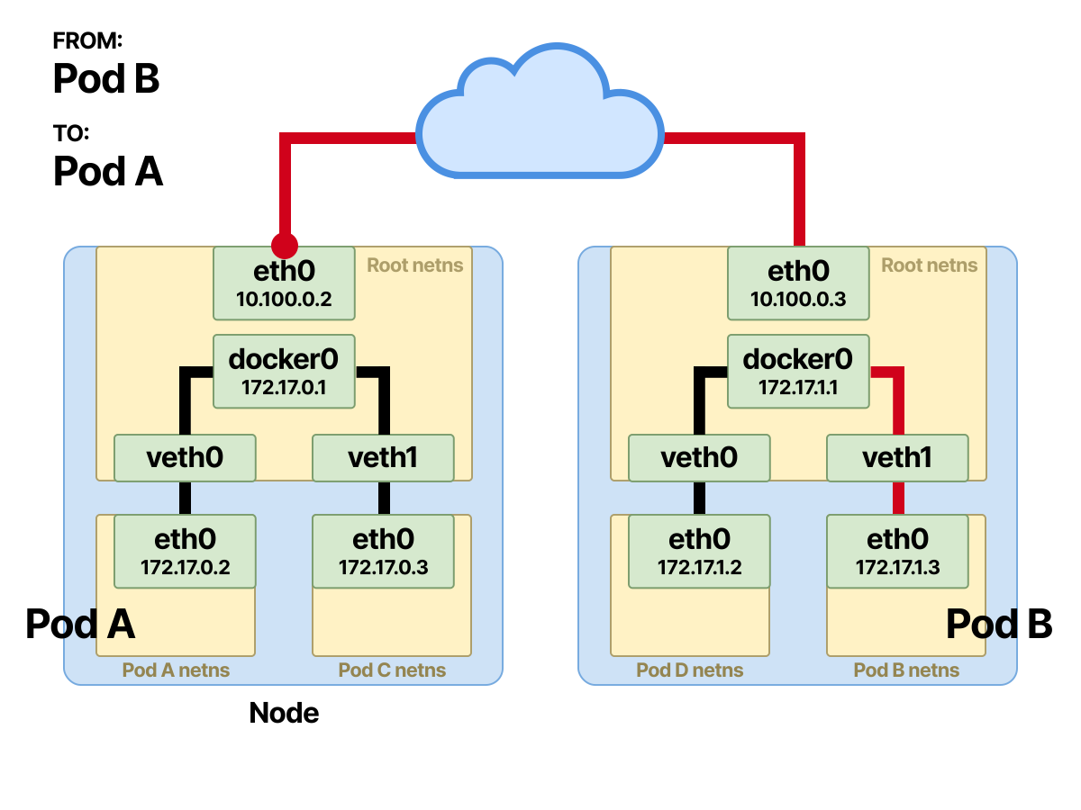
When the packet reaches the interface of the node where Pod-A resides, another NAT occurs.
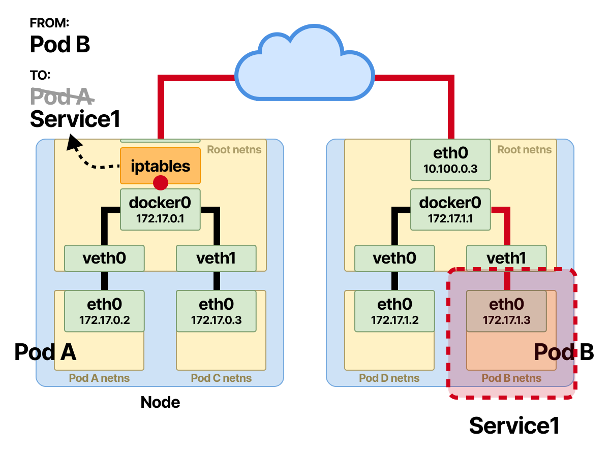
At this point, conntrack goes to work, modifying the source IP address; the iptables rule performs a SNAT, rewriting Pod-B’s source IP address to the original Service’s virtual IP.
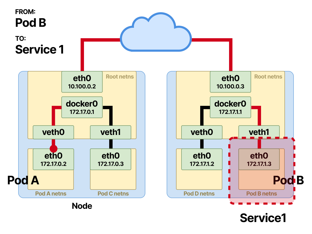
To Pod-A, the response comes from the Service rather than from Pod-B.
The rest is the same. Once the SNAT is complete, the packet reaches the bridge in the root namespace and is forwarded through the veth pair to Pod-A.
Summary
Let’s review the key points of this article together
- How containers communicate locally or within a Pod.
- How Pods on the same node and on different nodes communicate.
- Pod-to-Service — how a Pod sends traffic to a Pod behind a Service in Kubernetes.
- What namespaces, veth, iptables, chains, conntrack, Netfilter, CNI, and overlay networks are, and everything else you need in your Kubernetes networking toolbox.
