1. Background
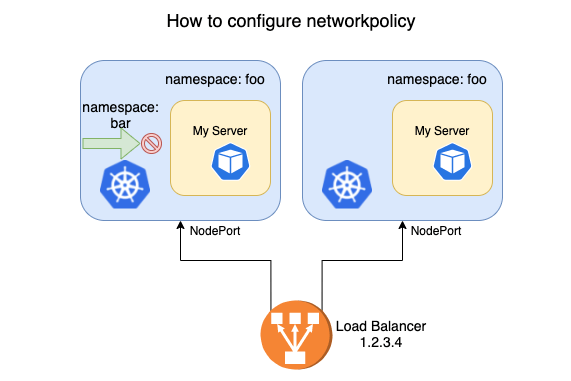
As shown above, the business team needs to isolate the services in a namespace, forbidding access from workloads in the bar namespace while allowing users to reach the service through a Load Balancer (LB) via NodePort. It is easy to write a network policy:
| |
However, traffic coming through the LB is blocked entirely, which is not what was expected. Search the technical community and the answer you may find is that Kubernetes NetworkPolicy mainly targets in-cluster access policies, while external traffic goes through SNAT, so its IP changes and can no longer match the policy.
Different network plugins use different modes, so the configuration differs. This article only offers one line of thinking: configuring an access policy for NodePort traffic using the common Calico IPIP mode as an example.
2. Prerequisites
2.1 NetworkPolicy in Kubernetes
In the document Kubernetes Network Isolation (with a Dozen-Plus Use Cases), I described Kubernetes NetworkPolicy and gave many examples.
NetworkPolicy is the network isolation object in Kubernetes, used to describe network isolation policies; the actual implementation depends on the network plugin. Today, network plugins such as Calico, Cilium, and Weave Net all support network isolation.
2.2 Several Working Modes of Calico
- BGP mode
In BGP mode, the BGP clients in the cluster interconnect pairwise and synchronize routing information.
- Route Reflector mode
In BGP mode, the number of client connections reaches N * (N - 1), where N is the number of nodes. This limits the scale of the cluster, and the community recommends no more than 100 nodes.
In Route Reflector mode, BGP clients do not need to synchronize routing information pairwise; instead they synchronize routing information to a few designated Route Reflectors. All BGP clients only need to establish connections with the Route Reflectors, so the number of connections grows linearly with the number of nodes.
- IPIP mode
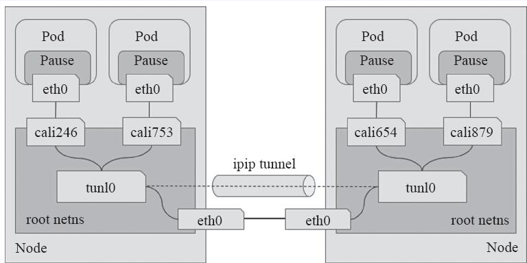
Unlike BGP mode, IPIP mode establishes tunnels between nodes through tunl0 to achieve network connectivity. The figure below describes the traffic between Pods in IPIP mode.
3. Why the Network Policy Does Not Take Effect
In the earlier document How to Get the Real Client IP in Kubernetes, I described how externalTrafficPolicy affects service traffic.
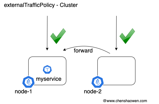
In Cluster mode, if you access node-2:nodeport, the traffic is forwarded to node-1, which has a service Pod.
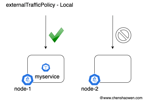
In Local mode, if you access node-2:nodeport, the traffic is not forwarded and the request cannot be answered.
Usually we use Cluster mode by default, and Cluster mode performs SNAT when forwarding traffic, that is, it modifies the source address. This causes the access request to miss the network policy, making it look as though the network policy never took effect.
Here we try two solutions:
- Add the post-SNAT source address to the access allowlist as well.
- Use Local mode. Since the LB has health checking, it can forward traffic to the node that has the service Pod, thereby preserving the source address.
4. NetworkPolicy Configuration Under NodePort
4.1 Test Environment
- Kubernetes version
v1.19.8
- kube-proxy forwarding mode
IPVS
- Node information
| |
- The workload under test
| |
The workload runs on node2.
- The service under test
| |
4.2 How NodePort Traffic Is Forwarded to the Pod
Two cases are mainly considered here.
- Accessing node1, which has no Pod workload
- Service forwarding rules
ipvsadm  -L

TCP  node1:31602 rr
  -> 10.233.96.32:9097            Masq    1      0          0

TCP  node1:31602 rr
  -> 10.233.96.32:9097            Masq    1      0          0

TCP  node1.cluster.local:31602 rr
  -> 10.233.96.32:9097            Masq    1      0          0

TCP  node1:31602 rr
  -> 10.233.96.32:9097            Masq    1      0          0

TCP  localhost:31602 rr
  -> 10.233.96.32:9097            Masq    1      0          0
As you can see, traffic accessing node1:31602 is forwarded to 10.233.96.32:9097, that is, the IP address and port of the service Pod.
- IP routing rules
Next, the routing rules. Access to the 10.233.96.0/24 subnet is all routed to tunl0, travels through the tunnel to node2, and is then routed into the service.
| |
- Accessing node2, which has the Pod workload
- Service forwarding rules
| |
Just as with node1, accessing the NodePort service on node2 is also forwarded to the IP address and port of the service Pod.
- Routing rules
But the routing rules are different: packets destined for 10.233.96.32 are sent to cali73daeaf4b12. cali73daeaf4b12 and the network interface inside the Pod form a veth pair, so the traffic is sent directly into the service Pod.
| |
From the output above we can see that if you access a node with no Pod workload, the traffic is forwarded through tunl0; if you access a node that has the Pod workload, the traffic is routed directly into the Pod without going through tunl0.
4.3 Option One: Add tunl0 to the Network Policy Allowlist
- Check the tunl0 information on each node
node1
| |
node2
| |
node3
| |
- Network policy configuration
| |
- Test verification
This does not meet expectations. All traffic passing through tunl0 is allowed. Workloads in the bar namespace can reach the service through node1:31602, node3:31602, and tekton-dashboard.tekton-pipelines.svc:9097 (workloads not on node2), so the traffic cannot be restricted.
4.4 Option Two: Use Local Mode
- Change the svc’s externalTrafficPolicy to Local mode
| |
- Deny all ingress traffic
| |
- Add the access allowlist
| |
- Test verification
This meets expectations. Using the network policy above satisfies the business requirement: access from the bar namespace is blocked, while external access forwarded through the LB to the NodePort is allowed.
5. Summary
Networking is a relatively hard part of Kubernetes to master, yet it is also an area with a broad and far-reaching impact on business. So spending a bit more time on networking is necessary and worthwhile.
This article, driven mainly by a business requirement, went further into explaining Calico’s network modes and solved the problem where SNAT changes the source IP so that NetworkPolicy does not behave as expected.
In Calico’s IPIP mode, an access policy for NodePort requires the externalTrafficPolicy: Local traffic forwarding mode. Then, following network policy best practices, deny all traffic first and add the allowlist policy afterward.
