I have been studying the infrastructure around model training lately, and I found that AI chip interconnect topology determines the scheduling and resource allocation of training cluster jobs. So I spent a little time putting together the common AI chip interconnect solutions.
1. Point-to-Point Interconnect
In a traditional PCIe system, data transfer between AI chips goes over PCIe, which cannot meet the demands of large-scale data transfer.
1.1 NVLink
NVLink is a high-speed interconnect between different GPUs within the same host.
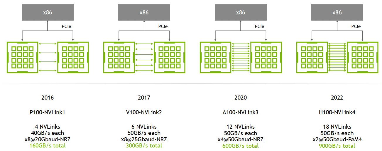
NVLink has evolved along with GPU architectures, from NVLink1 on P100 to NVLink4 on H100. As the figure shows, the differences between NVLink 1.0, NVLink 2.0, NVLink 3.0, and NVLink 4.0 come down to connection method, bandwidth, and performance.
| Product | Release Date | Card | Number of Links | Total Bandwidth Between GPUs | Architecture |
|---|---|---|---|---|---|
| NV Link 1.0 | 2016 | P100 | 4 | 160 GB/s | Pascal |
| NV Link 2.0 | 2017 | V100 | 6 | 300 GB/s | Volta |
| NV Link 3.0 | 2020 | A100 | 12 | 600 GB/s | Ampere |
| NV Link 4.0 | 2022 | H100 | 18 | 900 GB/s | Hopper |
| NV Link 5.0 | Expected 2025 | B200 | 18 | 1800 GB/s | Blackwell |
Note that you need to install the nvidia-fabricmanager service before using NVLink.
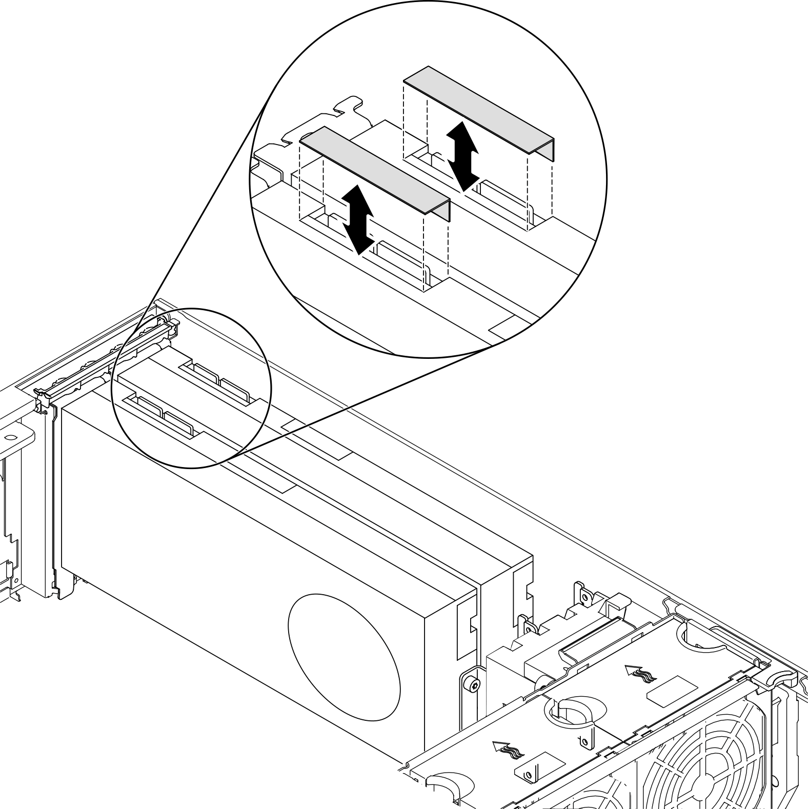
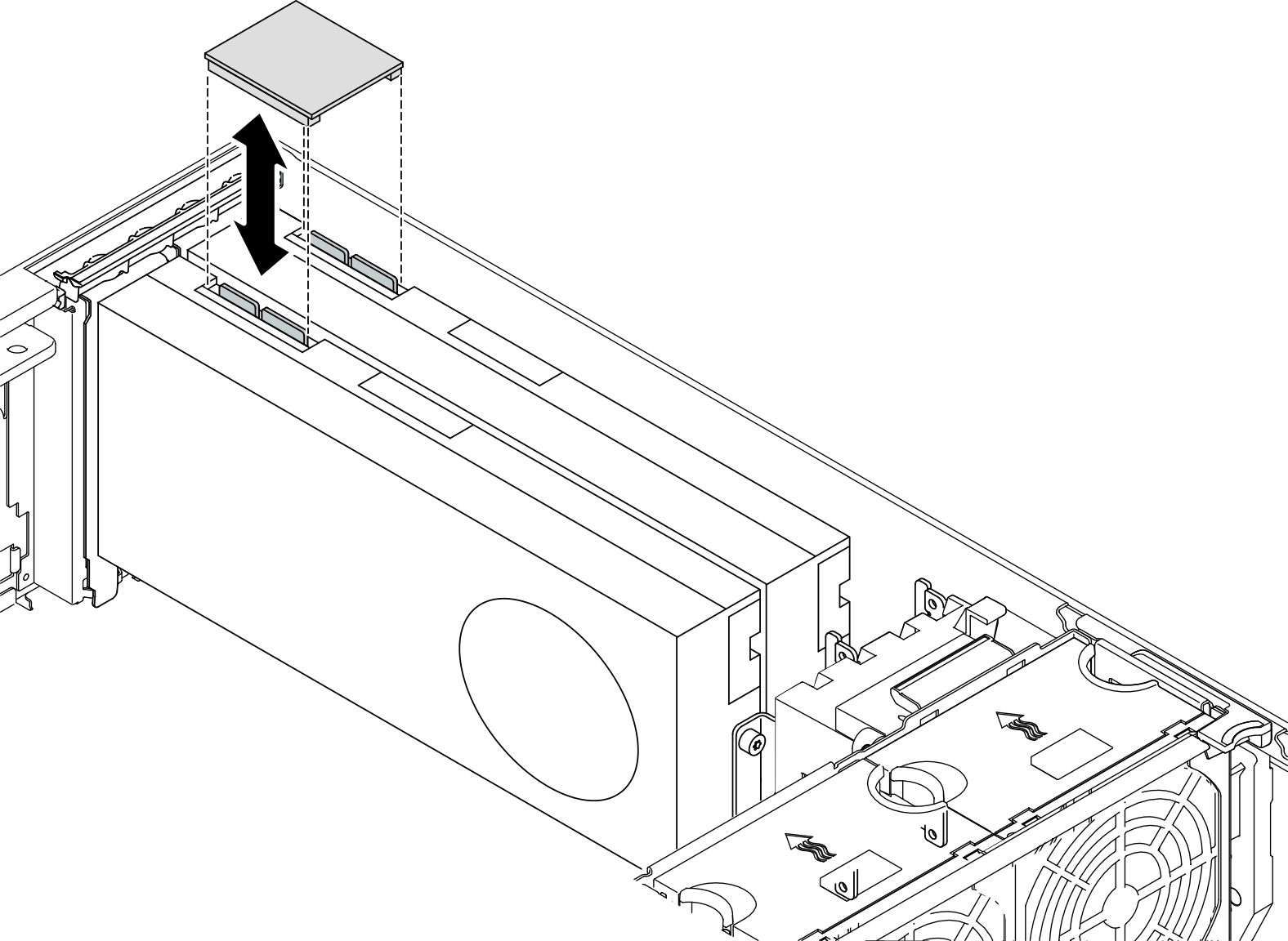
To get an intuitive picture, let’s look at how NVLink is installed in the chassis.
- Open the NVLink cover
- Adjust the orientation of the NVLink bridge and install it
1.2 HCCS
HCCS (High-speed Custom Communication System) is the high-speed interconnect technology Huawei designed for its Ascend series AI processors.
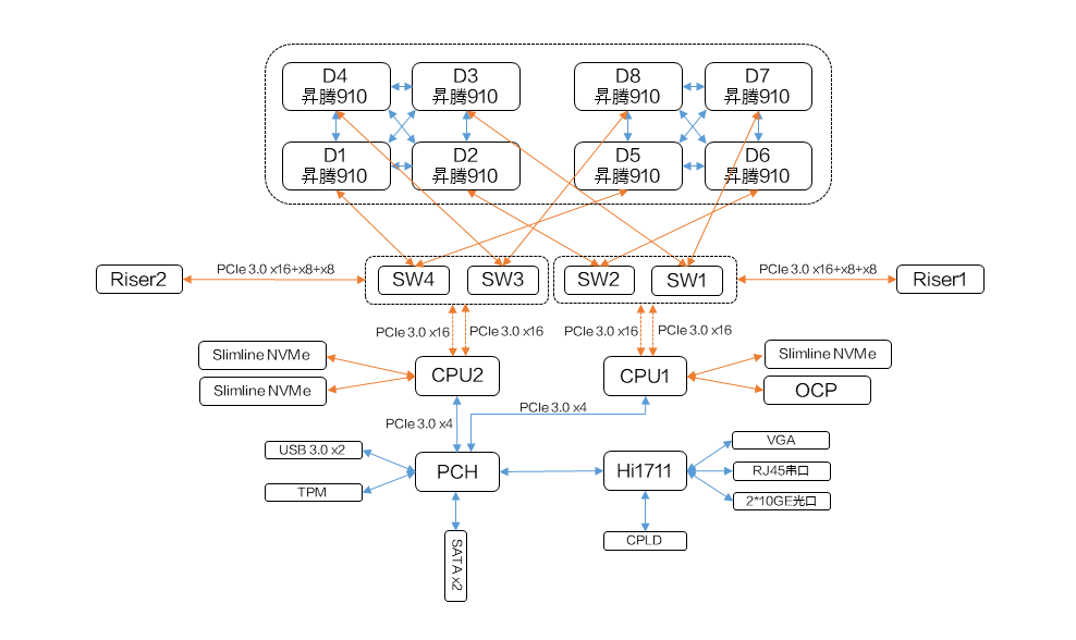
As shown above, a fully configured Atlas 800 training server contains two 910 boards, each with 4 910 NPUs. These NPUs are connected to each other via HCCS — the blue lines between the 910s in the figure — while connections between different boards use PCIe.
The 910B servers I have worked with also have two 910B boards, each with 8 910B NPUs. Let’s look at their topology:
| |
NPUs numbered 0 through 7 are interconnected pairwise via HCSS, while NPUs numbered 8 through 15 are interconnected pairwise via HCCS. When training models, we should try to keep the Pods of the same job running on the same board.
The 8 NPUs interconnected on each board share a total HCSS bandwidth of 392 GB/s, which means the bandwidth between two NPUs on the same board is 392/7 = 56 GB/s.
2. Multi-Point Networking
2.1 NVSwitch
NVSwitch is a switching chip from NVIDIA used to connect GPUs within a single host; it is an extension built on NVLink technology.
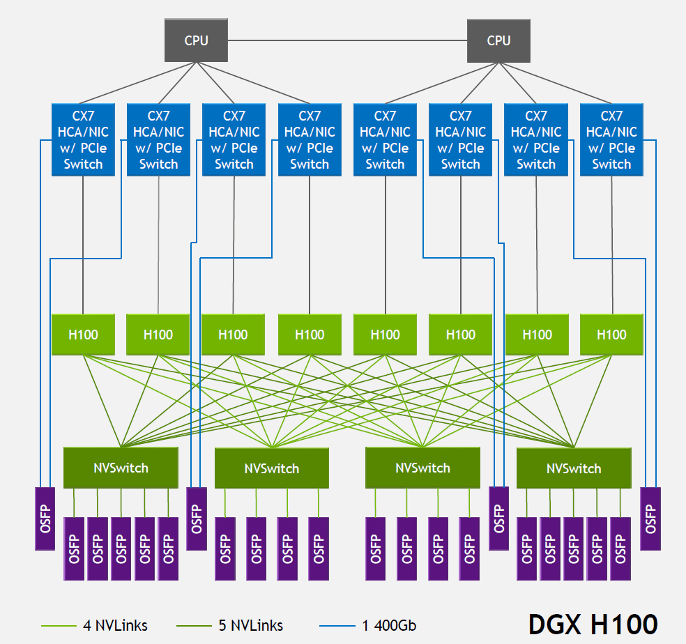
| Product | Max GPUs Directly Connected or per Node | Bandwidth Between GPUs | Architecture |
|---|---|---|---|
| NV Switch 1.0 | 8 | 300 GB/s | Volta |
| NV Switch 2.0 | 8 | 600 GB/s | Ampere |
| NV Switch 3.0 | 8 | 900 GB/s | Hopper |
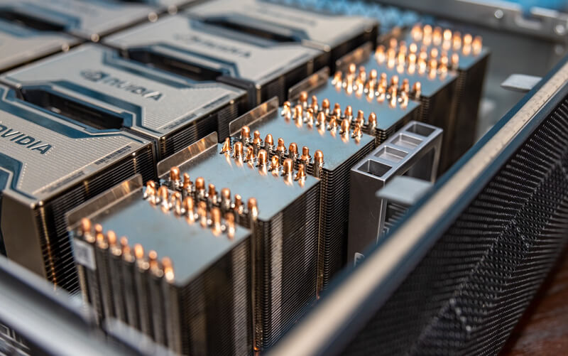
I could not find specific installation instructions online. In the figure above, the NVSwitch chips are the ones sitting under the 6 heatsinks. Once NVSwitch is installed, use NVLink cables to connect the NVSwitch to the GPU cards.
Using NVSwitch also requires installing the nvidia-fabricmanager service.
3. Cross-Node Interconnect
3.1 NVLink Switch
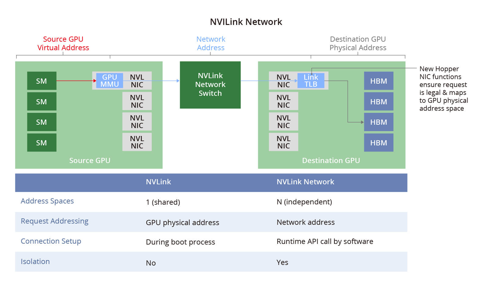
In 2022, NVIDIA spun the NVSwitch chip out as a standalone product and built it into an NVLink switch for connecting GPU devices between hosts.
The NVSwitch physical switch connects multiple NVLink GPU servers into one large Fabric network — an NVLink network — solving the bandwidth and efficiency problems of high-speed GPU-to-GPU communication. Each server has its own independent address space, providing data transfer, isolation, and security for the GPUs in the NVLink network.
3.2 InfiniBand Network
InfiniBand comes from an Israeli company called Mellanox, which NVIDIA acquired in 2020 for 6.9 billion USD.
InfiniBand is a network designed specifically for high-performance computing and data centers, offering high-bandwidth and low-latency communication. InfiniBand switches are typically used to build high-performance computing clusters, supporting features such as congestion control, virtual lanes, and multipath transmission.
InfiniBand network equipment has a high cost, but it delivers extreme performance.
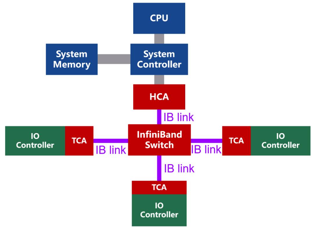
InfiniBand is a channel-based architecture whose building blocks fall into four main categories:
- HCA (Host Channel Adapter)
- TCA (Target Channel Adapter)
- InfiniBand link (the connection channel, which can be a cable or fiber, or an on-board link)
- InfiniBand switches and routers (used for networking)
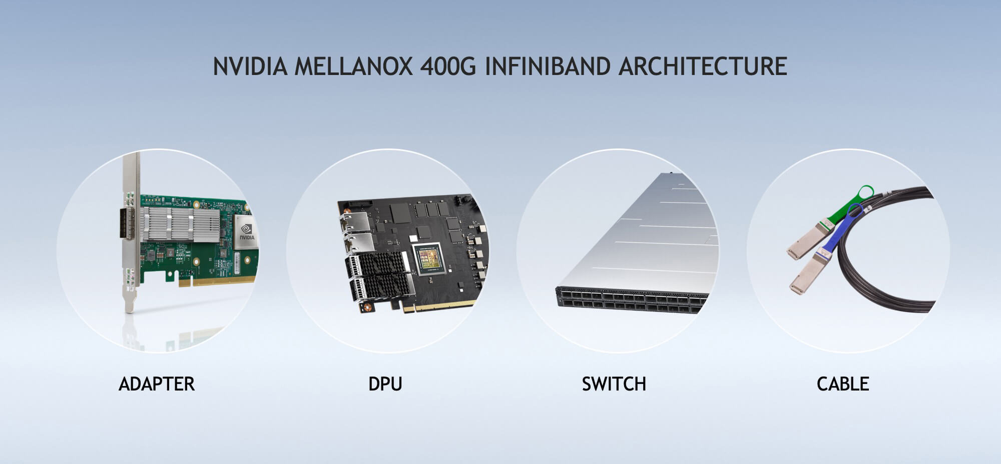
Building an InfiniBand network mainly requires four physical components:
- Adapter, used to connect servers to the InfiniBand network.
- DPU, the data processing unit, used to process data and relieve pressure on the CPU.
- Switch, used to connect multiple devices.
- Cable, used to connect Adapters, DPUs, and Switches.
A single InfiniBand cable costs over ten thousand, and building a large-scale cluster also requires deploying a Spine-Leaf network, so the cost of constructing a large-scale InfiniBand network is very high.
InfiniBand networks are widely used by supercomputer solutions and are common in data centers and high-performance computing clusters. InfiniBand bandwidth has steadily increased with technology, from the early SDR (1 Gbps), DDR (2 Gbps), QDR (4 Gbps), FDR (8 Gbps), EDR (16 Gbps), and HDR (32 Gbps), to NDR (100 Gbps), XDR (200 Gbps), and GDR (400 Gbps).
3.3 RoCE Network
RoCE is RDMA over Ethernet, an RDMA (Remote Direct Memory Access) technology built on Ethernet. It allows direct memory access over the network, reducing CPU load and improving data transfer efficiency.
RoCE has two versions: RoCE v1 and RoCE v2. RoCE v1 mainly implements RDMA at the Ethernet link layer, while RoCE v2 implements it at the UDP layer of the Ethernet TCP/IP protocol and introduces IP to solve scalability problems.
Compared with the RDMA channels of expensive InfiniBand components, RoCE is much cheaper.
But that cheapness applies only to hardware cost. RoCE’s labor cost is significantly higher than InfiniBand’s — it takes network experts to run it, dealing with all kinds of odd problems on NICs and switches.
Unless you are building a very large-scale cluster with tens of thousands of nodes and enough capital to invest, it is advisable to choose the almost maintenance-free InfiniBand network.
For building a RoCEv2 setup there are many optional devices, and compared with InfiniBand network devices they are significantly cheaper — you only need devices that support the RoCEv2 protocol.
In addition, InfiniBand NICs support two modes: InfiniBand and RoCE. An InfiniBand NIC can be used directly as a RoCEv2 NIC.
RoCE bandwidth depends on the Ethernet standard in use. RoCE v1 typically runs on 10 Gbps or 40 Gbps Ethernet networks, while RoCE v2 can run on higher-speed networks such as 25 Gbps, 40 Gbps, 50 Gbps, or even 100 Gbps.
3.4 Spine-Leaf Network
In data centers, a Spine-Leaf network is often used together with InfiniBand NICs to build high-performance computing clusters.
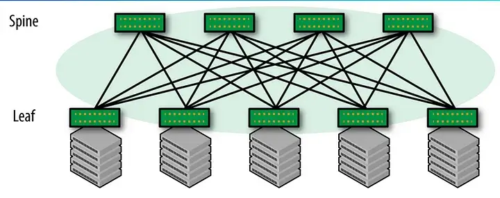
The Spine layer is the backbone of the network; the Leaf layer connects terminal devices such as servers and storage. Usually both the Spine layer and the Leaf layer are built with Layer 3 switches.
The Spine-Leaf network architecture provides high-bandwidth, low-latency, non-blocking server-to-server connectivity. The advantages of a Spine-Leaf network include:
- Easy horizontal scaling. The network can be scaled horizontally without changing the topology, by adding Spine and Leaf nodes to expand its size.
- Non-blocking design. Every Leaf connects to every Spine switch, ensuring that communication between any two nodes is not affected by other traffic.
- Few network hops. Any two endpoints are at most three hops apart: Leaf - Spine - Leaf.
- Simple network structure, with only two tiers, making it easy to manage and maintain.
A typical data transfer process:
Servers under the same Leaf node. When communication stays within the same Leaf node, data is forwarded directly through that Leaf node without going through a Spine node.
Servers under two different Leaf nodes. Data travels from the source server through its Leaf switch to a Spine switch, is then forwarded by the Spine switch to the Leaf node where the destination resides, and from there is forwarded through the Leaf node to the destination server.
In a Spine-Leaf network, the maximum bandwidth between two servers depends on the following factors:
- Server NIC bandwidth
- Leaf switch port bandwidth and backplane bandwidth
- Spine switch port bandwidth and backplane bandwidth
- Bandwidth of the Spine-Leaf connections
If Ethernet is used, Spine-Leaf network bandwidth depends on the Ethernet standard; if an InfiniBand network is used, Spine-Leaf network bandwidth depends on the bandwidth of the InfiniBand network.
